Basic Tutorial
This tutorial is designed as a quick start guide to give you an overview of the most commonly used LeoCAD features without going too deep on any particular topic. Throughout these exercises, you will create aracecar and driver and learn to:
- Browse the parts library and add new pieces to a model.
- Move and rotate pieces.
- Create a model with multiple steps.
- Change the view position and orientation.
- Select objects.
If you have not installed LeoCAD yet, please visit the Download Page before continuing.
Getting Started
Launch the LeoCAD application and you will see a window that looks somewhat like this:
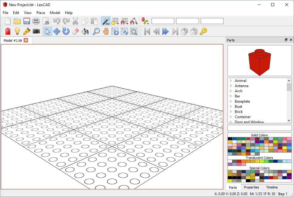
LeoCAD presents a standard graphical user interface: a title bar, menus and toolbars at the top, a status bar along the bottom, a workspace to the left and tool windows to the right.
On the left, the workspace area is where one or more views of your model are displayed. To the right is a tool window that shows a list of available parts with a preview picture of the currently selected part and a palette of available colors. There are additional tool windows that are available for other operations, but they will not be featured in this tutorial.
Note that the user interface varies between operating systems, so if you are not running the Windows version of LeoCAD, your application will slightly differ from what is shown in the pictures.
Browsing the Parts List
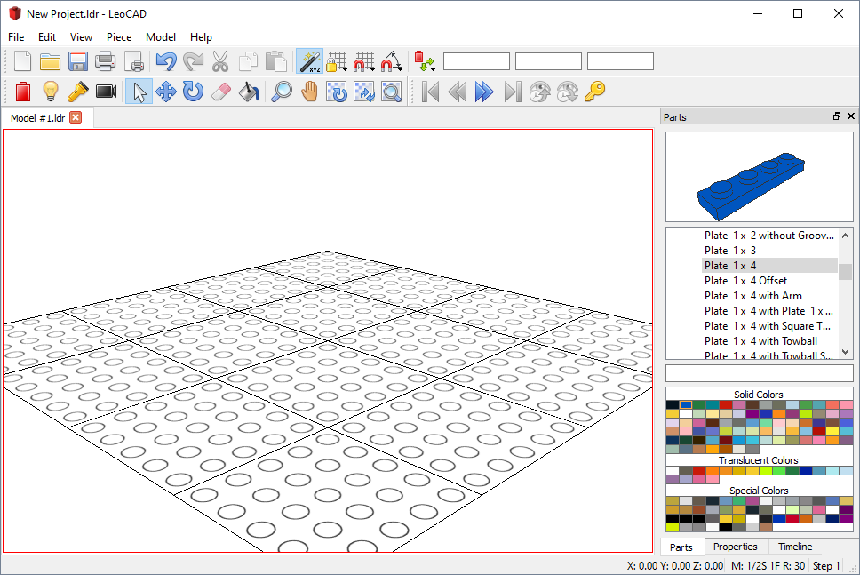
Start building the car by adding a blue “Plate 1 x 4”:
Scroll down the “Parts” list (by default, this is displayed along the right edge of the workspace) until you find the “Plate” group, then expand that group and select “Plate 1 x 4”.
Now click on the blue rectangle in the “Colors” tool window just below the “Parts” list and you will notice that the image in the top right corner changes as you select different parts or change colors to reflect your current choices.
Adding a Piece
Add the “Plate 1 x 4” to your model:
There several ways to add a piece to a model; the easiest one is to simply drag it from the “Parts” list into the “Model View”. While dragging the piece, you will see a preview of where it will be placed as you move the mouse.
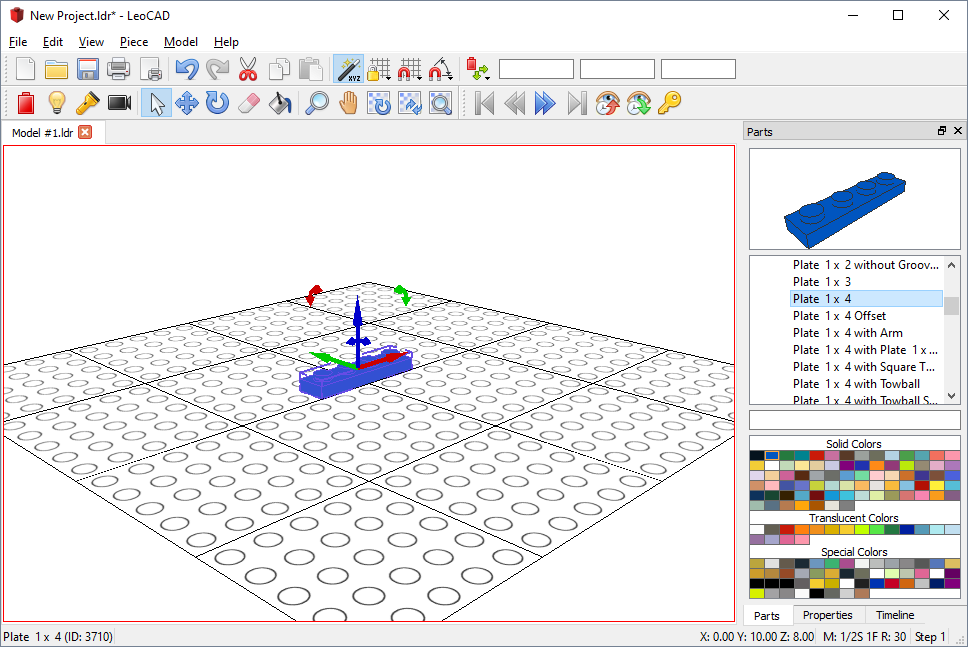
Tip: Alternatively, you can press the “Insert” key on your keyboard or use the “Insert” function on the toolbar.
Moving Pieces
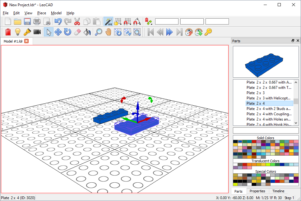
Now add a blue “Plate 2 x 4”:
Select “Plate 2 x 4” from the “Parts” list and add it next to the piece you added earlier. It should be exactly 2 studs apart from the first piece, so if you did not drop it in the correct position, you will have to adjust it now.
Move your mouse over the arrows on top of the “Plate 2 x 4” and notice that when it is over one of them, it will turn yellow, and the mouse pointer will change to an icon with 4 arrows. This means that if you hold the “Left Mouse Button” down now and move the mouse, the currently selected pieces will move along the line where the arrow is.
Tip: You can also use the arrow, “Page Up” or “Page Down” keys on your keyboard or “Move” on the toolbar to move pieces.
Tip: The grid is very useful to quickly measure the distance between pieces.
Rotating Pieces
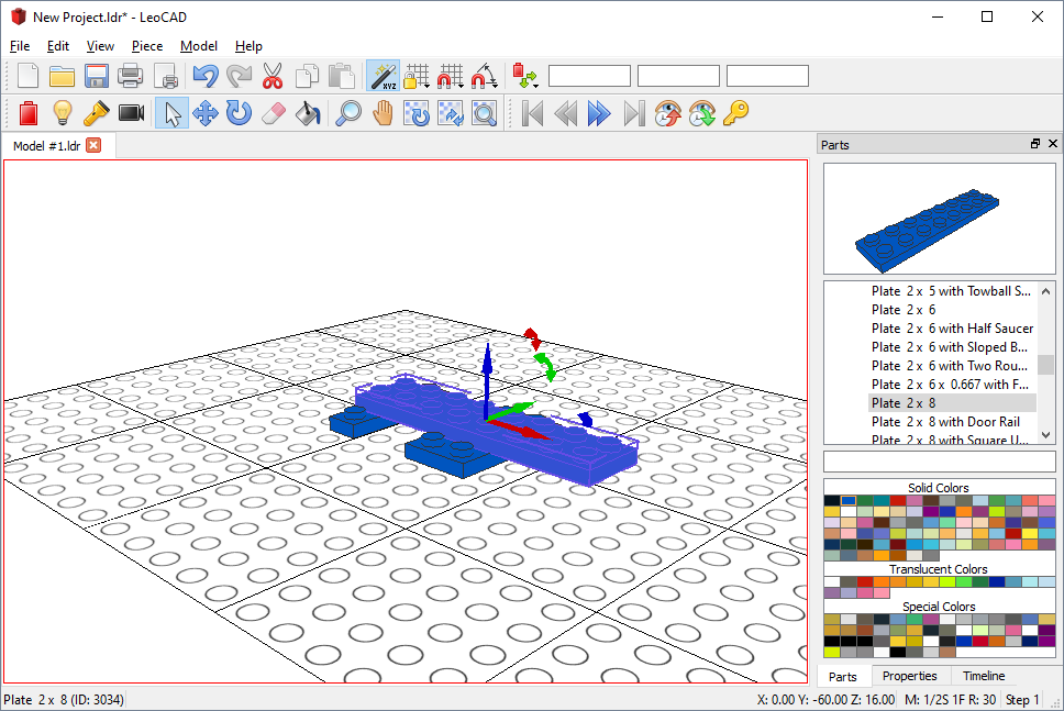
Add a blue “Plate 2 x 8” on top of the previous 2 pieces:
When you first drag the piece into the model, it will be parallel to the first pieces, but we want it to be perpendicular to them, so we will need to rotate it by 90 degrees.
Move your mouse over to “Rotate” (the curved blue arrow) on the toolbar and drag the part to rotate the piece, similar to what you did to move the pieces in the previous step. You will also have to move the new piece so that it is on top of the previous pieces.
Tip: You can also use the keyboard to rotate on all axes by holding the “Shift” key down while pressing the arrow, “Page Up” or “Page Down” keys.
Building Steps
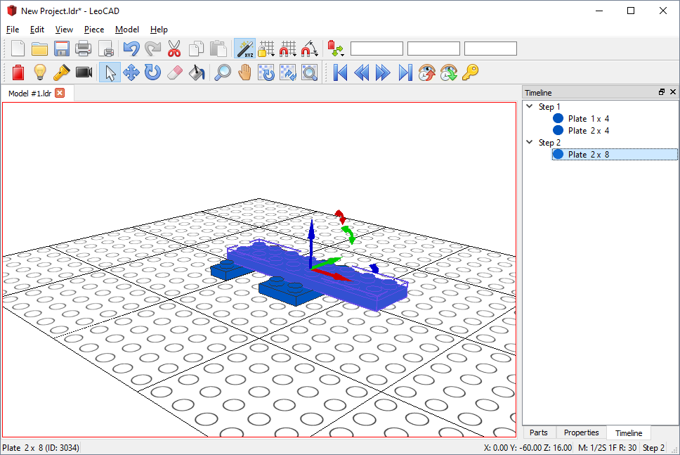
Building instructions are usually broken up into multiple steps so that people can easily understand how a model is built, so let us move on to “Step 2” of our model by clicking on “Next” (double right arrow) on the toolbar. Notice that the current step is shown on the “Status Bar” in the bottom right corner of the main window.
Now go to the “Timeline” pane (under the “Parts” list) and you will be able to see the step where each piece was added to the model. To make it easier for someone else to build our car, let us move the “Plate 2 x 8” to “Step 2” by dragging it on the “Timeline” from “Step 1” to “Step 2”.
If you go back to “Step 1” in the instructions by clicking on “Previous” (double left arrows), you will see that the “Plate 2 x 8” is not visible there anymore and only appears on “Step 2” or later.
Tip: You can also press the “Left” and “Right” arrow keys while holding down the “Alt” key on your keyboard to move between steps.
Searching for Parts
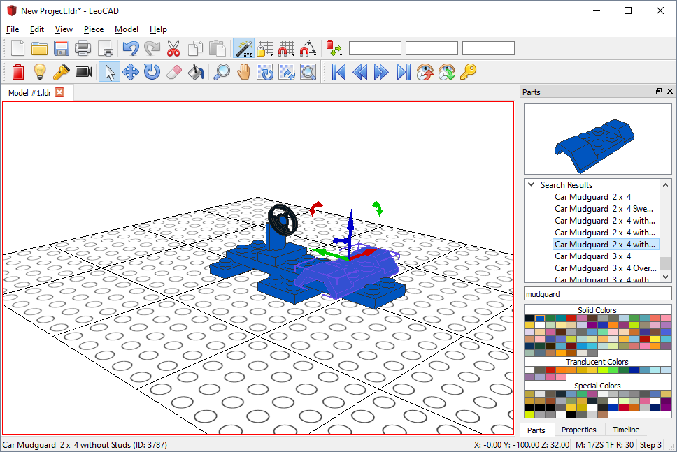
Now go to “Step 3” of the instructions and let us add a steering wheel and mudguards next. If you are not familiar with naming convention of the “Parts” list, it can take a while to find out which category a part belongs to, so let us use the “Search Parts” feature to find those parts.
Type “mudguard” in the “Search Parts” box and press “Enter” and LeoCAD will search all parts for the text you typed and display the results under the “Search Parts” box at the bottom portion of the “Parts” list.
Select "Car Mudguard 2 x 4 without Studs" and add it to the model, then do the same for the steering wheel and you’ll have something like this:
Adding More Pieces
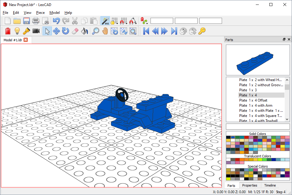
Advance the instructions another step and add a “Slope Brick 45 2 x 2” above the mudguard and another to the front of the car.
Let us also add another “Plate 1 x 4” to the car; here is the picture of the almost complete car:
Rotating the View
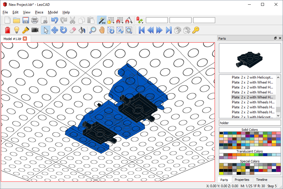
Now we need to add wheels to the car, so let us start by adding the wheel holders to “Step 5”. It is not going to be easy to see the bottom of the car from the current position, so let us rotate the camera to get a better view.
Hold the “Alt” key down on your keyboard while you drag the mouse by using the “Left Mouse Button” and the view will rotate. With “Alt” pressed, dragging with the “Middle Mouse Button” will pan the view sideways, and dragging with the “Right Mouse Button” will zoom in and out.
Once you have a good view position, add 2 black "Plate 2 x 2 with Wheel Holders" to the car:
Tip: The buttons and keys for these shortcuts can be configured in the “Preferences” menu.
Movement Snap
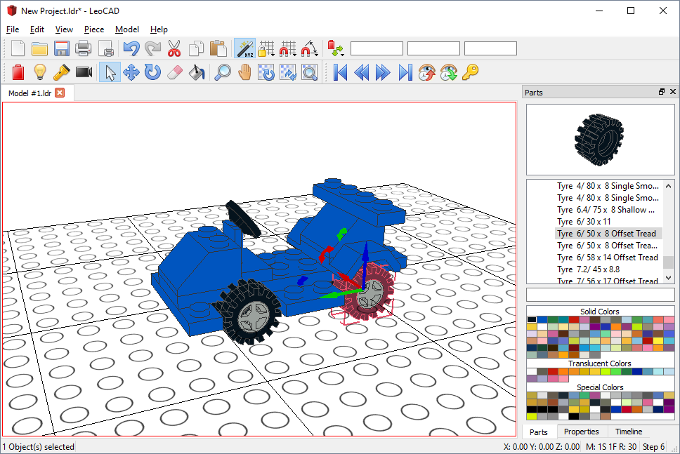
Go to “Step 6” and add a grey "Wheel Rim 6.4 x 8" and a black "Tyre 6/50 x 8 Offset Tread".
If you zoom in closer, you will notice that with the default movement increments, it is not possible to get the wheel to align correctly with the wheel holder, so you will have to deselect “Move Snap Enabled” by clicking on the “Movement Snap” (left magnet icon) on the toolbar
Select both the tyre and wheel at the same time by holding down the “Control” key on the keyboard and clicking on each piece and then move them to the correct position of the car.

Tip: The current movement increments are shown on the “Status Bar”.
Copy and Paste
We still need 3 more sets of wheels, but instead of adding new tyres and wheels one at a time, we can save time by copying the ones we just added to the clipboard and pasting it back. It works like most other applications--use keyboard shortcuts or the “Edit” menu to copy and paste to the clipboard.
When you paste a copy, it is placed in the same position as the one you copied it from, so we need to move the new parts to the other side of the car. Since the car is exactly four studs wide, you can reselect “Movement Snap Enabled” and set its value to “1 Stud” by clicking “Snap XY” in the “Movement Snap” menu to easily position the new wheel on the other side of the car.
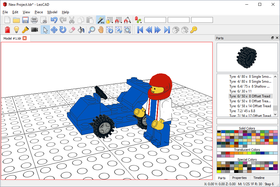
We still need one last thing to finish the project--a driver! Advance another step and select “Minifig Wizard” from the “Piece” menu and you will see a dialog where you can customize a minifig. Select the colors and accessories you want and click “OK” to add the driver.
The finished car should look something like this:
This completes the tutorial. Please remember that this tutorial does not teach you how to use the advanced features of the LeoCAD; this is just an introduction to the basic features.
Do not forget to save the file in case you want to come back and play with it later or send it to a friend. You can also print the instructions or have LeoCAD create a web page with them for you--just explore all the options you have in the menus. You can even create ray-traced pictures and use them as your desktop wallpaper if you have POV-Ray installed!